Description
xMGBS set AR, M23, emergency stop, two pushbuttons, door hinge on left
- \n
- Locking module with handle module suitable for doors hinged on the left \n
- Series connection possible (up to 20 AR devices in series)\n \n
- Short circuit monitoring \n
- 2 safety outputs (semiconductor outputs) \n
- Up to category 4/PL e according to EN ISO 13849-1 \n
- Emergency stop \n
- 2 pushbuttons (illuminated) \n
- With plug connector M23 \n
- Unicode \n
- Door monitoring output \n
Specifications
x| MGBS-L1 | Guard locking actuated by spring force and power-ON released (closed-circuit current principle). |
Lens set
The color of the pushbuttons can be selected using the color cover set included (5 colors).
Connector assignment
| Plug connector (view of connection side) | Pin | Designation | Function | Connecting cable conductor coloring |
|---|---|---|---|---|
 |
1 | IMP | Solenoid operating voltage, 24 V DC | VT |
| 2 | FI1A | Enable input, channel A | RD | |
| 3 | FI1B | Enable input, channel B | GY | |
| 4 | FO1A | Safety output, channel A | RD/BU | |
| 5 | FO1B | Safety output, channel B | GN | |
| 6 | UB | Electronics operating voltage, 24 V DC | BU | |
| 7 | RST | Reset input | GY/PK | |
| 8 | OD | Door position monitoring output | GN/WH | |
| 9 | OI | Diagnostic monitoring output | YE/WH | |
| 10 | S1.A1 | EMERGENCY STOP (channel A) | GY/WH | |
| 11 | S1.A2 | EMERGENCY STOP (channel A) | BK | |
| 12 | FE | Functional earth (must be connected to meet the EMC requirements) | GN/YE | |
| 13 | S1.B1 | EMERGENCY STOP (channel B) | PK | |
| 14 | S1.B2 | EMERGENCY STOP (channel B) | BN/GY | |
| 15 | S2 | Pushbutton 2 (illuminated) | BN/YE | |
| 16 | H2 | LED 2 | BN/GN | |
| 17 | S3 | Pushbutton 3 (illuminated) | WH | |
| 18 | H3 | LED 3 | YE | |
| 19 | 0 V | Electronics and solenoid operating voltage, 0 V DC | BN |
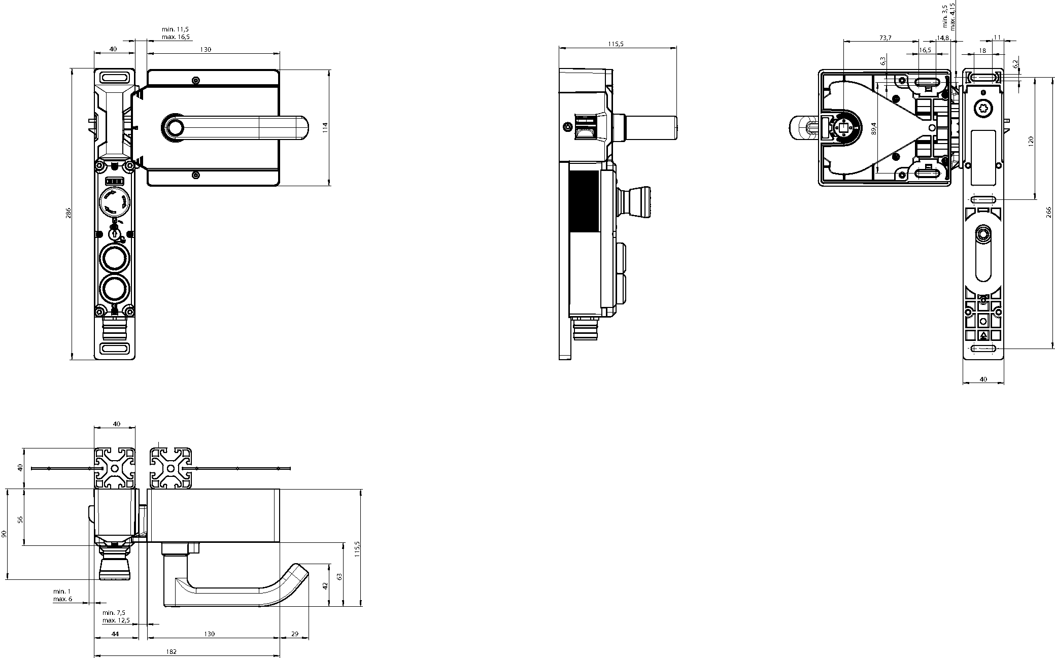
Dimension drawing MGBS set without escape release

Wiring diagram

Dimensional drawings

Connection examples

Mechanical values and environment
| Installation orientation | Door hinge DIN right |
| Degree of protection | IP65 |
| Ambient temperature | -20 to 55 °C |
| Material | Housing: Fiber glass reinforced plastic, nickel-plated die-cast zinc, stainless steel |
Miscellaneous
| Product version number | V1.0.0 |
| Additional feature | with automatic lockout mechanism |
Locking modules MGBS-P-L1-AR-U-R-AZE-SH-159171 (Order no. 159171)

Workspace
| Repeat accuracy R | according to EN 60947-5-2 | 10 % |
Operating and display elements
| Item | Color | Extras | Slide-in label | Version | Switching element | Note slide-in label | Number | Designation1 | LED |
|---|---|---|---|---|---|---|---|---|---|
| 1 | Emergency stop | 2 PD | |||||||
| 2 | Illuminated pushbutton | 1NO | |||||||
| 3 | Illuminated pushbutton | 1NO |
Electrical connection values
| Fuse | |
| External (solenoid operating voltage IMP) | 0.5 - 8 A |
| External (operating voltage UB) | 0.25 - 8 A |
| Power consumption | 6 W |
| Rated insulation voltage Ui | 50 V |
| Rated impulse withstand voltage Uimp | 0.5 kV |
| Operating voltage DC | UUB: 24 V DC -15% - +15% reverse polarity protected, regulated, residual ripple<5%, PELV |
| EMC protection requirements | Acc. to EN IEC 60947-5-3 |
| Utilization category | DC-13: 24 V 150 mA (Caution: outputs must be protected with a free-wheeling diode in case of inductive loads) |
| Solenoid operating voltage DC | UIMP: 24 V DC -15% - +10% reverse polarity protected, regulated, residual ripple<5%, PELV |
| Solenoid duty cycle | 100 % |
| Risk time according to EN 60947-5-3 | max. 260 ms |
| Risk time according to EN 60947-5-3, extension for each additional device | max. 5 ms |
| Switching load according to UL | 24V DC, Class 2 (alternatively, see operating instructions) |
| Safety class EN IEC 61140 | III |
| Current consumption | IUB: 40 mA, IIMP: 400 mA |
| Test pulse duration | max. 1.0 ms (Applies to a load with C<= 30 nF and R<= 20 kohm) |
| Test pulse interval | min. 140 ms |
| Degree of contamination (external, according to EN 60947-1) | 3 |
Controls and indicators
| Operating voltage | UB V |
| Operating current | 1 - 50 mA |
| Power supply LED | 24 V |
| Current consumption LED | 10 mA |
Emergency stop
| Breaking capacity | max. 0.25 W |
| Switching voltage | 5 - 24 V |
| Switching current | 1 - 100 mA |
Monitoring output OD, OI
| Output type | p-switching, short circuit-proof |
| Output voltage | 0.8xUB - UB V DC |
| Switching current | 1 - 50 mA |
Safety outputs FO1A / FO1B
| Output type | 2 semiconductor outputs, p-switching, short circuit-proof |
| HIGH U(FO1A) / U(FO1B) | UB-1.5 - UB V DC |
| LOW U(FO1A) / U(FO1B) | 0 - 1 V DC |
| Discrepancy time (both safety outputs) | max. 10 ms Acc. to EN IEC 60947-5-3 |
| Turn-on time | max. 400 ms |
| Off-state current Ir | max. 0.25 mA |
| Switching current (per safety output FO1A / FO1B) | 1 - 150 mA |
Mechanical values and environment
| Approach speed | max. 20 m/min |
| Connection type | 1 plug connector M23, 19-pin, RC18 |
| Extraction force | 20 N |
| Ready delay | 8 s |
| Actuating force | 10 N |
| Installation orientation | Door hinge DIN right |
| Switching frequency | max. 0.5 Hz |
| Mechanical life | 1 x 10⁶ |
| Overtravel | 5 mm |
| Retention force | 20 N |
| Shock and vibration resistance | Acc. to EN IEC 60947-5-3 |
| Degree of protection | IP65 (screwed tight plug connector/mating component) |
| Ambient temperature (with UB = 24 V DC) | -20 to 55 °C |
| Material | Switch bracket: Die-cast zinc, Safety switch housing: Reinforced thermoplastic |
| Locking force Fmax | 3900 N |
| Locking force FZh | 3000 N (Fzh = Fmax/1.3, depending on the actuator used) |
| Guard locking principle | Closed-circuit current principle |
Downloads
Documents
Operating Instructions MGBS-P-L.-AR… Unicode/Multicode
Other Documents
Shipping Details
| Item designation | MGBS-P-L1H-AR-U-R-SH-161563 |
| Gross weight | 3.8kg |
| Customs tariff number | 85371098 |
| ECLASS | 27-27-24-05 Safety-related transponder switch with guardlocking |
Documents
x- Choosing a selection results in a full page refresh.